|
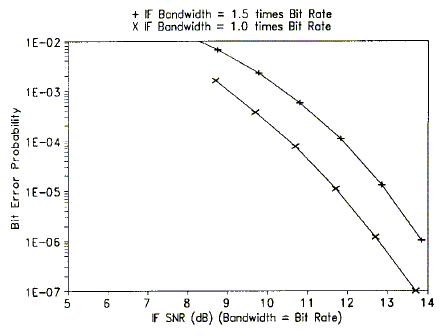
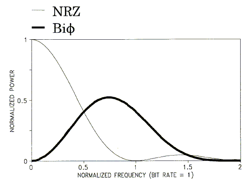
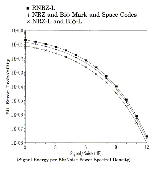
PCM STANDARDS ADDITIONAL INFORMATION AND RECOMMENDATIONS 1.0 Bit Rate Versus Receiver Intermediate-Frequency Bandwidth 2.0 Recommended PCM Synchronization Patterns 3.0 Spectral and BEP Comparisons 4.0 PCM Frame Structure Examples Footnotes 1.0 Bit Rate Versus Receiver Intermediate-Frequency Bandwidth The following subparagraphs contain information about selection of receiver intermediate-frequency (IF) bandwidths. Additional information is contained in RCC document 119, Telemetry Applications Handbook. 1.1 The standard receiver IF bandwidth values are listed in table 2-1. Not all bandwidths are available on all receivers or at all test ranges. Additional bandwidths may be available at some test ranges. The IF bandwidth, for data receivers, should typically be selected so that 90 to 99 percent of the transmitted power spectrum is within the receiver 3 dB bandwidth. 1.2 For reference purposes, in a well-designed PCM/FM system (NRZ-L data code) with peak deviation equal to 0.35 times the bit rate and an IF bandwidth (3 dB) equal to the bit rate, a receiver IF signal-to-noise ratio (SNR) of approximately 13 dB will result in a bit error probability (BEP) of 10 -6. A 1 dB change in this SNR will result in approximately an order of magnitude change in the BEP. The relationship between BEP and IF SNR in a bandwidth equal to the bit rate is illustrated in figure C-1 for IF bandwidths equal to the bit rate and 1.5 times the bit rate. An approximate expression for the BEP is  Figure C-1. BEP versus IF SNR in bandwidth = bit rate for NRZ-L PCM/FM. where  Other data codes and modulation techniques have different BEP versus SNR performance characteristics. 1.3 It is recommended that the maximum period between bit transitions be 64-bit intervals to ensure adequate bit synchronization. Table C-1 contains recommended frame synchronization patterns for general use in PCM telemetry. 2.0 Recommended PCM Synchronization Patterns Table C-1 contains recommended frame synchronization patterns for general use in PCM telemetry. Patterns are shown in the preferred order of transmission with "111" being the first bit sequence transmitted. This order is independent of data being LSB or MSB aligned. The technique used in the determination of the patterns for lengths 16 through 30 was essentially that of the patterns of 2n binary patterns off a given length, n, for that pattern with the smallest total probability of false synchronization over the entire pattern overlap portion of the ground station frame synchronization 15. The patterns for lengths 31 through 33 were obtained from a second source 16. 3.0 Spectral and BEP Comparisons for NRZ and Bi Figure C-2 shows the power spectral densities of baseband NRZ and Bi    4.0 PCM Frame Structure Examples Figures C-4, C-5, and C-6 show examples of allowable PCM frame structures. In each example, the Minor Frame Sync Pattern is counted as one word in the minor frame. The first word after the Minor Frame Sync Pattern is word 1. Figures C-5 and C-6 show the preferred method of placing the subframe ID counter in the minor frame. The counter is placed before the parameters that are referenced to it. Major Frame Length is as follows: |
| Figure C-4 - Major Frame Length = | Minor Frame Maximum Length. |
| Figure C-5 - Major Frame Length = | Minor Frame Maximum Length multiplied by Z. |
| Figure C-6 - Major Frame Length = | Minor Frame Maximum Length multiplied by Z. |
|
Appendix C Footnotes 15. A more detailed account of this investigation can be found in a paper by J. L. Maury, Jr. and J. Styles, "Development of Optimum Frame Synchronization Codes for Goddard Space Flight Center PCM Telemetry Standards," in Proceedings of the National Telemetering Conference, June 1964. 16. The recommended synchronization patterns for lengths 31 through 33 are discussed more fully in a paper by E. R. Hill, "Techniques for Synchronizing Pulse-Code Modulated Telemetry," in Proceedings of the National Telemetering Conference, May 1963. 17. Material presented in paragraph 3.0 is taken from a study by W. C. Lindsey (University of Southern California), Bit Synchronization System Performance Characterization, Modeling and Tradeoff Study, Naval Missile Center Technicall Publication. |