|
IRIG 106-99 CHAPTER 7 - MAGNETIC TAPE STANDARDS 7.1 General 7.2 Definitions 7.3 General Requirements for Standard Instrumentation Tapes and Reels 7.4 General Characteristics of Instrumentation Tapes and Reels 7.5 Physical Characteristics of Instrumentation Tapes and Reels 7.6 Instrumentation Tape Magnetic and Electrical Characteristics 7.7 General Requirements for 19-mm Digital Cassette Helical Scan Recording Tape and Cassettes 7.8 General Requirements for 1/2-Inch Digital Cassette Helical Scan Recording Tape and Cassettes Footnotes MAGNETIC TAPE STANDARDS 7.1 General These standards define terminology, establish key performance criteria, and reference test procedures for longitudinally-oriented oxide, unrecorded magnetic tape designed for instrumentation recording 1, and reference specifications for 19 mm (0.75 in) cassettes designed for digital helical scan recording and S-VHS cassettes designed for 12.65 mm (1/2 in) digital helical scan recording. Classes of instrumentation recording tapes include High Resolution (HR) tapes used for wide band recording, High Density Digital (HDD) tapes used for high density digital PCM recording, and High Energy (HE) tapes used for double density recording. Coercivities of HR and HDD tapes are in the range of 275 to 350 oersteds. High energy tapes have coercivities of 600 to 800 oersteds. Nominal base thickness is 25.4 Tm (1.0 mil) and nominal coating thickness is 5 Tm (200 microinches) for all tapes. Where required, limits are specified to standardize configurations and to establish the basic handling characteristics of the tape. Limits placed on the remaining requirements must be determined by the tape user in light of the intended application and interchangeability requirements imposed on the tape (see table 7-4 for examples of suggested requirement limits). 7.2 Definitions 7.2.1 Back Coating 7.2.2 Base 7.2.3 Bias Level 7.2.4 Bi-Directional 7.2.5 Binder 7.2.6 Blocking 7.2.7 Center Tracks 7.2.8 Dropout 7.2.9 Edge Tracks 7.2.10 Erasure 7.2.11 E-Value 7.2.12 High-Density Digital Magnetic Tape 7.2.13 High-Energy Magnetic Tape 7.2.14 High-Resolution Magnetic Tape 7.2.15 Layer-to-Layer Signal Transfer (Print Through) 7.2.16 Magnetic Oxide Coating 7.2.17 Manufacturer's Centerline Tape 7.2.18 Manufacturer's Secondary Centerline Tape 7.2.19 Modulation Noise 7.2.20 Record Level 7.2.21 Scatterwind 7.2.22 Shedding 7.2.23 Short Wavelength Output Uniformity 7.2.24 Upper Band Edge 7.2.25 Wavelength Response 7.2.26 Working Length 7.2.27 Working Reference Tape Underlined terms appearing within definitions indicate that these terms are defined elsewhere in paragraph 7.2. For the purpose of this standard, the following definitions apply. 7.2.1 Back Coating. A thin coating of conductive material (for example, carbon) bonded to the surface of a magnetic tape opposite the magnetic-coated surface for reducing electrostatic charge accumulation and for enhancing high-speed winding uniformity. Resistivity of the back coating should be 1 megohm per square or less, whereas the oxide-coated magnetic surface resistivity is much higher (also see magnetic oxide coating). 7.2.2 Base. The material on which the magnetic oxide coating (and back coating, if employed) is applied in the manufacture of magnetic tapes. For most applications, polyester-base materials are currently employed. 7.2.3 Bias Level. The level of high frequency ac bias current or voltage in a direct record system needed to produce a specified level of an upper band edge (UBE) frequency sine-wave signal at a particular tape speed. Usually adjusted to produce maximum output or increased beyond maximum to depress the output 2 dB. 7.2.4 Bi-Directional. Ability of a magnetic tape to record and to reproduce a specified range of signals within specified tolerances of various characteristics when either end of the tape on the reel is used as the leading end. 7.2.5 Binder. Material in which the magnetic oxide particles or back-coating particles are mixed to bond them to the base material. 7.2.6 Blocking. Failure of the magnetic coating to adhere to the base material because of layer-to-layer adhesion in a wound tape pack. 7.2.7 Center Tracks. On a recorded tape, center tracks are those which are more than one track distance from either edge of the tape, for example, tracks 2 through 13 of a 14-track tape or tracks 2 through 27 of a 28-track tape. 7.2.8 Dropout. A reproduced signal of abnormally low amplitude caused by tape imperfections severe enough to produce a data error. In digital systems, dropouts produce bit errors. 7.2.9 Edge Tracks. The data tracks nearest the two edges of a recorded magnetic tape, for example, tracks 1 and 14 of a 14-track tape. 7.2.10 Erasure. Removal of signals recorded on a magnetic tape to allow reuse of the tape or to prevent access to sensitive or classified data. Instrumentation recorders and reproducers do not usually have erase heads, so bulk erasers or degaussers must be employed. 7.2.11 E-Value. The radial distance by which the reel flanges extend beyond the outermost layer of tape wound on a reel under a tape tension of 3.33 to 5.56 newtons (12 to 20 ounces of force) per inch of tape width. Inadequate E-value may prohibit the use of protective reel bands. 7.2.12 High-Density Digital Magnetic Tape. Instrumentation magnetic tape with nominal base thickness of 25.40 Tm (1 mil) and coercivity of 275 to 350 oersteds used to record and reproduce high-density digital (PCM) signals with per-track bit densities of 590 b/mm (15 kb/in.) or greater. 7.2.13 High-Energy Magnetic Tape . Magnetic tapes having coercivity of 600 to 800 oersteds and nominal base thickness of 25.4 Tm (1 mil) used for double density analog recording and high-density digital recording above 980 b/mm (25 kb/in.). 7.2.14 High-Resolution Magnetic Tape. Instrumentation magnetic tape used for recording on wide band recorder and reproducer systems. The HR and HDD tapes may have identical coatings and coercivities (275 to 350 oersteds) but differ in the extent and type of testing conducted by the manufacturer. 7.2.15 Layer-to-Layer Signal Transfer (Print Through). Transfer of a signal to a layer of a wound magnetic tape originating from a signal recorded on an adjacent layer of tape on the same reel. Saturation-level recorded signals and tape storage at elevated temperatures are likely contributors to this effect. 7.2.16 Magnetic Oxide Coating . Material applied to a base material to form a magnetic tape. The magnetic oxide coating contains the oxide particles, the binder, and other plasticizing and lubricating materials necessary for satisfactory operation of the magnetic tape system (also see back coating). 7.2.17 Manufacturer's Centerline Tape. A tape selected by the manufacturer from his production, where the electrical and physical characteristics are employed as reference standards for all production tapes to be delivered during a particular contractual period. Electrical characteristics include, but are not limited to, bias level, record level, output at 0.1 UBE, and wavelength response. The MCTs are not usually available for procuring agency use. 7.2.18 Manufacturer's Secondary Centerline Tape. A tape selected by a manufacturer from his production and provided in lieu of an MCT. On the MSCT, the electrical characteristics may depart from the MCT characteristics, but calibration data referenced in the MCT are provided. All other characteristics of the MSCT are representative of the manufacturer's product. 7.2.19 Modulation Noise. Noise riding on a reproduced signal that is proportional to the amplitude of the recorded signal (below saturation) and results from tape-coating irregularities in particle size, orientation, coercivity, and dispersion. 7.2.20 Record Level. The level of record current or voltage required to achieve a specified reproduce output level with bias level previously set to the correct value. In direct record systems, standard record level is the level of a 0.1 UBE frequency signal required to produce 1 percent third harmonic distortion in the reproduced output signal because of tape saturation. 7.2.21 Scatterwind. Lateral displacements of tape wound on a reel which gives an irregular appearance to the side surfaces of a tape pack. Scatterwind can result from such things as poorly controlled tape tension, guiding, static electrical charge, and poor tape slitting. 7.2.22 Shedding. Loss of magnetic coating from tape during operation on a tape transport. Excessive shedding causes excessive dropout. 7.2.23 Short Wavelength Output Uniformity. A measure of high-frequency reproduce signal amplitude uniformity caused by oxide coating variations. 7.2.24 Upper Band Edge. The highest frequency that can be recorded and reproduced at a particular tape speed in the direct record mode. The UBE signals are used in setting bias level; 0.1 UBE signals are used to set record level. 7.2.25 Wavelength Response . The record and reproduce characteristic of a magnetic tape which depends on tape formulation, coating thickness, and other tape physical parameters and is a function of the wavelength recorded on the tape (tape speed divided by signal frequency) rather than the actual frequency recorded. 7.2.26 Working Length. Length of tape usable for reliable recording and reproduction of data. Actual tape length on a reel exceeds the working length to provide for tape start and stop at each end of the reel without loss of data. 7.2.27 Working Reference Tape . A tape or tapes of the same type as an MCT or MSCT selected by the user and calibrated to the MCT or MSCT. The working reference tapes (WRT) are employed in conducting tests on tape types during a procurement activity and for aligning and testing recorder and reproducer systems to minimize running the MCT or MSCT. 7.3 General Requirements for Standard Instrumentation Tapes and Reels 7.3.1 Reference Tape System 7.3.1.1 Manufacturer's Centerline Tape 7.3.1.2 Manufacturer's Secondary Centerline Tape 7.3.1.3 Working Reference Tape 7.3.1.4 Test Recorder and Reproducer 7.3.1.5 MCT/MSCT/WRT Use 7.3.2 Marking and Identifying 7.3.3 Packaging 7.3.4 Winding 7.3.5 Reels and Hubs 7.3.6 Radial Clearance (E-Value) 7.3.7 Flammable Materials 7.3.8 Toxic Compounds The following subparagraphs describe the requirements for tapes and reels. 7.3.1 Reference Tape System . To establish a set of test procedures which can be performed independently and repeatably on different manufacturers' tape transports, a centerline reference tape system employing Manufacturer's Centerline Tapes (MCT), Manufacturer's Secondary Centerline Tapes (MSCT) or Working Reference Tapes (WRT) as required, should be used. The reference tape system provides a centerline tape against which tape or tape recorder specifications may be tested or standard tapes for aligning operational recorders. 7.3.1.1 Manufacturer's Centerline Tape. The electrical characteristics provided for a manufacturer's centerline tape include, but are not limited to, bias level, record level, wavelength response, and output at 0.1 UBE wavelength. The physical characteristics of the MCT shall also represent the manufacturer's production and shall be representative of all production tape delivered during any resultant contractual period (see subparagraph 7.2.17). 7.3.1.2 Manufacturer's Secondary Centerline Tape. On the MSCT, the electrical characteristics are calibrated to the manufacturer's reference tape, and calibration data are supplied with the MSCT. The physical characteristics of the MSCT shall represent the manufacturer's production (see subparagraph 7.2.18). 7.3.1.3 Working Reference Tape . Working reference tapes shall be of the same type as those under procurement or test and shall be used in place of a MCT or MSCT for all applicable test procedures (see subparagraph 7.2.27). |
 The MCT or MSCT shall be a full-length tape of 25.4 mm (1 in.) width,
wound on a 266.7 mm (10 1/2 in.) or 355.6 mm (14 in.) reel or as
designated by the tape user. The center one-third of the working tape
length shall be used as the calibrated working area.
|
|
7.3.1.4 Test Recorder and
Reproducer. A laboratory quality test recorder shall be designated
for use with the reference tape system during any magnetic tape procurement
and test program. The recorder selected shall meet the requirements in
chapter 6. 7.3.1.5 MCT/MSCT/WRT Use. Using MCT or MSCT as a reference, the tape user performs all tests necessary to determine if the manufacturer's centerline performance values meet operational and recorder requirements. All acceptable centerline tapes are retained by the tape user as references in subsequent acceptance test procedures performed in support of resultant contracts or contractual periods. A working reference tape, which has been calibrated to an MCT or MSCT, is used as the actual working reference in the applicable testing procedures outlined in volume III, RCC document 118. Dropout tests should use a tape other than the MSCT or WRT. 7.3.2 Marking and Identifying . See Federal Specification W-T-1553A. 7.3.3 Packaging. Specified by user. 7.3.4 Winding. The tape shall be wound on the reel or hub with the oxide surface facing toward the hub ("A" wind). The front of the wound reel is defined as that flange visible when viewing the tape reel with the loose end of the tape hanging from the viewer's right. 7.3.5 Reels and Hubs. Reels and hubs shall conform to the tape user specified requirements of Federal Specification W-R-175 (also see appendix D). 7.3.6 Radial Clearance (E-Value) . For all tape lengths, use 3.175 mm (0.125 in.) (see subparagraph 7.2.11). 7.3.7 Flammable Materials. Flammable materials shall not be a part of the magnetic tape. Flammable materials will ignite from a match flame and will continue to burn in a still carbon dioxide atmosphere. 7.3.8 Toxic Compounds. Compounds which produce toxic effects in the environmental conditions normally encountered under operating and storing conditions as defined in subparagraph 7.4.2 shall not be part of the magnetic tape. Toxicity is defined as the property of the material which has the ability to do chemical damage to the human body. Highly toxic or corrosive compounds produced under conditions of extreme heat shall be identified and described by the manufacturer. 7.4 General Characteristics of Instrumentation Tapes and Reels 7.4.1 Dimensional Specifications 7.4.2 Environmental Conditions 7.4.2.1 Tape Storing Conditions 7.4.2.2 Operating Environment 7.4.2.3 Non-operating Environment 7.4.3 Other Characteristics The following subparagraphs describe the general characteristics for tapes and reels. 7.4.1 Dimensional Specifications . Magnetic tape shall be supplied on flanged reels in the standard lengths, widths, and base thicknesses outlined in table 7-1 . Reel and hub diameters are taken from Federal Specification W-R-175. |
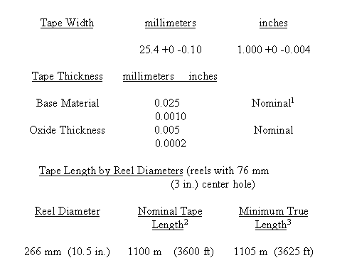 1. Actual tape base material thickness slightly less because of manufacturing conventions. 2. Original dimensions are in feet. Metric conversions are rounded for convenience. 3. Tape-to-flange radial clearance (E-value) is 3.18 mm (0.125 in.). |
|
7.4.2 Environmental Conditions
. The tape shall be able to withstand, with no physical damage or
performance degradation, any natural combination of operating or non-operating
conditions as defined in subparagraphs 7.4.2.1 and 7.4.2.2. 7.4.2.1 Tape Storing Conditions . Magnetic tape is subject to deterioration at temperature and humidity extremes. In some cases the damage is reversible, but irreversible damage may occur, especially with long-term storage in unfavorable conditions. 7.4.2.2 Operating Environment . Recommended limits: |
| Condition | Range | |
| Temperature: | 4 to 30 °C (40 to 85 °F) |
|
| Humidity: | 20 to 60 percent relative humidity (RH)
noncondensing |
|
| Pressure: | Normal ground or aircraft operating altitude pressures. For very high altitudes, tape users should consult with manufacturers to determine if tape and recorder compatibility is affected by low atmospheric pressure. |
 (1) Binder/oxide system tends to become sticky and unusable above 50 °C
(125 °F).
(1) Binder/oxide system tends to become sticky and unusable above 50 °C
(125 °F).(2) At low humidities, tape binder and oxide system tends to dry out, and oxide and binder adhesion can be unsatisfactory. Brown stains on heads may appear below 40 percent RH. (3) At high humidities, abrasivity is increased and other performance problems may arise. |
|
7.4.2.3 Non-operating Environment
. Temperature and Relative Humidity. |
|
Short Term - 0 to 45 °C (32 to 115 °F) and 10 to 70 percent RH
noncondensing Long Term - 1 to 30 °C (33 to 85 °F) and 30 to 60 percent RH noncondensing |
 Experience has shown that with long exposure to temperatures below freezing,
lubricants and plasticizers tend to migrate out of the oxide coating resulting
in poor lubrication and gummy surface deposits.
|
|
7.4.3 Other Characteristics
. Storage life, bi-directional performance, frictional vibration, and
scatterwind characteristics shall conform to Federal Specification
W-T-1553[SH] unless otherwise specified by the tape user at the time of
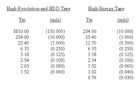
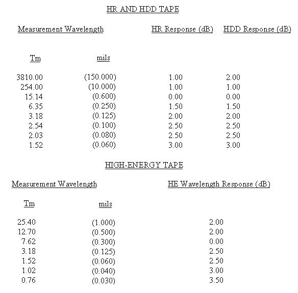
purchase. 7.5 Physical Characteristics of Instrumentation Tapes and Reels As specified in Federal Specification W-T-1553A and W-R-175. 7.6 Instrumentation Tape Magnetic and Electrical Characteristics 7.6.1 Bias Level 7.6.2 Record Level 7.6.3 Wavelength Response 7.6.4 Output at 0.1 UBE Wavelength 7.6.5 Short Wavelength Output Uniformity 7.6.6 Dropouts 7.6.7 Durability 7.6.8 Modulation Noise 7.6.9 Layer-to-Layer Signal Transfer 7.6.10 Erasure Ease 7.6.11 Suggested Tape Requirement Limits The following subparagraphs describe required magnetic and electrical tape characteristics. 7.6.1 Bias Level. The bias level (see subparagraph 7.2.3) required by the magnetic tape shall not differ from the bias level requirements of the reference tape by more than the amount specified by the tape user. The test procedure outlined in subparagraph 7.3.1, Bias Level, volume III of RCC document 118 shall be used to determine compliance with this requirement. 7.6.2 Record Level. The record level (see subparagraph 7.2.20) required by the magnetic tape shall not differ from the record level requirements of the reference tape by more than the amount specified by the tape user. The test procedure outlined in subparagraph 7.3.2, Record Level, volume III of RCC document 118 shall be used to determine compliance with this requirement. 7.6.3 Wavelength Response. The output of the magnetic tape, measured at the wavelength values listed in table 7-2, Measurement Wavelengths, shall not differ from the output of the reference tape by more than the amounts specified by the tape user. Wavelength response requirements shall be specified in terms of output after having normalized the output to zero decibels at the 0.1 UBE wavelength. The test procedure outlined in subparagraph 7.3.3, Wavelength Response and Output at 0.1 Upper Band Edge Wavelength, volume III of RCC document 118 shall be used to determine compliance with this requirement (see table 7-4A, Suggested Wavelength Response Requirements). |
TABLE 7-2. MEASUREMENT WAVELENGTHS |
 |
|
7.6.4 Output at 0.1 UBE Wavelength
. The wavelength output of the magnetic tape shall not differ from the
0.1 UBE wavelength of the reference tape by more than the amount specified by
the tape user. The test procedure outlined in subparagraph 7.3.3, Wavelength
Response and Output at 0.1 Upper Band Edge Wavelength, volume III of RCC
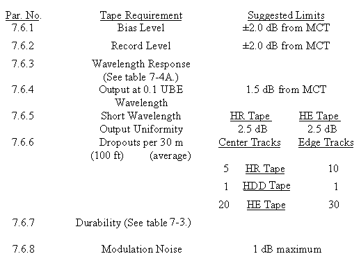
document 118 shall be used to determine compliance with this requirement. 7.6.5 Short Wavelength Output Uniformity . The short wavelength output of the magnetic tape shall be sufficiently uniform that a signal recorded and reproduced throughout the working tape length in either direction of longitudinal tape motion shall remain free from long-term amplitude variation to the extent specified by the tape user. The test procedure outlined in subparagraph 7.3.4, Short Wavelength Output Uniformity, volume III of RCC document 118 shall be used to determine compliance with this requirement. 7.6.6 Dropouts. The instantaneous nonuniformity (dropout) output of a recorded signal, caused by the magnetic tape, shall not exceed the center-track and edge-track limits specified by the tape user on the basis of dropouts per 30.48 m (100 ft.) of nominal working tape length. The nominal dropout count shall be determined by totaling all the dropouts per track over the working tape length and dividing by the total number of 30.48 m (100 ft.) intervals tested. A second method of specifying the allowable dropout count is to specify the maximum number per track for each 30.48 m (100 ft.) interval tested. This method may be preferred if critical data is recorded in specific areas of the working tape length, but a specified number of dropouts per hundred feet greater than the average values may be expected. |
 Dropout test results are very dependent on the tape transport used for the
test and will vary from run to run on a given transport. Edge tracks tend
to contain more dropouts than the center tracks, and more dropouts are
allowed on the edge tracks. Refer to table 7-4.
|
|
7.6.6.1 For High Resolution (HR) tapes, a dropout is defined
as a 6 dB reduction in amplitude for a period of 5 microseconds or more of a 1
MHz sine-wave signal recorded and reproduced at a tape speed of 3048 mm/s
(120 ips). Signal losses of 6 dB or more which exceed the 5 microsecond time
period shall constitute a dropout count for each 5 microsecond time period
occurring in the given signal loss. Track definitions are given in
subparagraphs 7.2.7 and
7.2.9. The test procedure outlined in subparagraph 7.1.3.3, volume III of
RCC document 118 shall be used to determine compliance with this requirement.
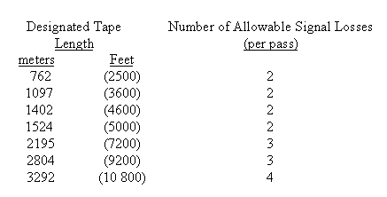
7.6.6.2 For High Density Digital (HDD) tapes, a dropout is defined as a 10 dB or greater reduction in amplitude for a period of 1 microsecond or more of a square-wave test signal of maximum density recorded and reproduced at 3048 mm/s or 1524 mm/s (120 ips or 60 ips). On at least every other track (7 tracks of the odd head on a 28-track head assembly (alternatively, every other track of the even head) record and reproduce a square-wave test signal of 2 MHz at 3048 mm/s (120 ips) or 1 MHz at 1524 mm/s (60 ips). The record level shall be set slightly above saturation by adjusting the record current to produce maximum reproduce output and increasing the record current until the output signal is reduced to 90 percent of maximum. For playback, a reproduce amplifier and a threshold detector shall be used. The signal-to-noise ratio of the test signal at the input to the threshold detector shall be at least 25 dB, and the detector shall detect any signal loss of 10 dB or more below reference level. The reference level shall be established by averaging the test signal output level over a 10 m (30.8 ft.) nominal tape length in the vicinity of a dropout. 7.6.6.3 For each of the seven tracks tested, the accumulated duration in microseconds of detected dropout events shall be displayed and used to directly display the dropout rate for each track scaled appropriately for the tape working length. Signal losses of 10 dB or more which exceed the 1 microsecond time period shall constitute a dropout count for each microsecond time period occurring in the given signal loss. 7.6.6.4 For high-energy tapes, a dropout is defined as for high-resolution tapes except that a 2 MHz signal is used. 7.6.7 Durability. The magnetic tape shall resist deterioration in magnetic and electrical performance because of wear to the coating surface. Signal losses, as defined below, caused by surface wear shall not occur in excess of the per-pass limits specified in table 7-3 for the first 35 passes. |
 |
|
Signal losses in excess of those limits specified above shall not occur during
either a record, record and reproduce or uninterrupted reproduce pass of the
working tape length. Signal loss is a reduction in signal amplitude of 3 dB
or greater for a time period of 3 through 10 seconds of a recorded and
reproduced short wavelength signal. Where a continuous loss of signal of 3 dB
or greater exceeds the 10-second time period, a signal loss count shall be
required for every sequential 10-second time period occurring in the given
signal loss. The test procedure outlined in subparagraph 7.3.6, Durability,
volume III of RCC document 118 shall be used to determine compliance with this
requirement. 7.6.8 Modulation Noise. The amplitude modulation superimposed upon a recorded and reproduced signal by the magnetic tape shall not exceed the limits specified by the tape user. The test procedure outlined in subparagraph 7.3.7, Modulation Noise, volume III of RCC document 118 shall be used to determine compliance with this requirement. 7.6.9 Layer-to-Layer Signal Transfer . A signal resulting from layer-to-layer signal transfer shall be reduced in amplitude from the original signal a minimum of 40 dB for 25.4 Tm (1.0 mil) tape and 46 dB for 38.1 Tm (1.5 mils) tape. The test procedure outlined in subparagraph 7.3.8, Layer-to-Layer Signal Transfer, volume III of RCC document 118 shall be used to determine compliance with this requirement. 7.6.10 Erasure Ease. For HR and HDDR tapes, an erase field of 79.58 kA/M (1000 oersteds) shall effect at least a 60 dB reduction in output amplitude of a previously recorded 25.4 Tm (1.0 mil) wavelength signal. For HE tapes, an erase field of 160 kA/m (2000 oersteds) shall effect at least a 60 dB reduction of a previously recorded 25.4 Tm (1.0 mil) wavelength signal. The test procedure outlined in subparagraph 7.3.9, Ease of Erasure, volume III of RCC document 118 shall be used to determine compliance with this requirement. 7.6.11 Suggested Tape Requirement Limits . Table 7-4 lists some suggested limits to be used for instrumentation tape. |
 |
 |
|
7.7 General Requirements for 19-mm Digital
Cassette Helical Scan Recording Tape and Cassettes 7.7.1 Magnetic Tape 7.7.2 19-mm Cassettes 7.7.1 Magnetic Tape. The magnetic tape shall meet the requirements of MML Document 94-1, Specification for Rotary Instrumentation Magnetic Recording Tape, 19-millimeter (0.75 inch) Wide, 68 KA/M (850 Oersteds)2 . 7.7.2 19-mm Cassettes. The recorder/reproducers shall be capable of using 19 mm cassettes that conform to the physical dimensions of medium and large cassettes as defined in SMPTE 226M3. 7.8 General Requirements for 1/2-Inch Digital Cassette Helical Scan Recording Tape and Cassettes 7.8.1 Magnetic Tape 7.8.2 1/2-Inch Cassettes 7.8.1 Magnetic Tape. The magnetic tape shall meet the requirements of MML Document 93-1, Specification for Rotary Instrumentation Magnetic Recording Tape, 12.65 millimeter (0.5 inch), 68 KA/M (850 Oersteds) 4. 7.8.2 1/2-Inch Cassettes. The recorder/reproducers shall be capable of using 1/2-inch cassettes that conform to the physical dimensions as defined in ANSI V98.33M-1983 5. To ensure crossplay compatibility, the T-160 (327 meters, min.) is recommended. Chapter 7 Footnotes 1. Federal Specifications W-T-1553A and W-R-175 may be used to replace paragraphs contained in this chapter where applicable. High output and HDD tapes are not included in the Federal Specifications. Other standards are referenced in paragraph 1.0, appendix D. 2. MML Document 94-1 is available from the Naval Air Warfare Center Aircraft Division, Warminster, Pennsylvania 18974-0591. 3. SMPTE 226M is available from the Society of Motion Picture and Tele-vision Engineers, 595 West Hartdale Avenue, White Plains, New York 10607. 4. MML Document 93-1 is available from the Naval Air Warfare Center, Aircraft Division, Warminster, Pennsylvania 18974-0591. 5. ANSI V98.33M-1983 is available from American National Standards Institute, 1430 Broadway, New York, New York 10018. |