|
IRIG 106-99 CHAPTER 6 - MAGNETIC TAPE RECORDER AND REPRODUCER STANDARDS, Continued.... 6.1 Introduction 6.2 Definitions 6.3 General Consideration for Longitudinal Recording 6.4 Recorded Tape Format 6.5 Head and Head Segment Mechanical Parameters 6.6 Head Polarity 6.7 Magnetic Tape and Reel Characteristics 6.8 Direct Record and Reproduce Systems 6.9 Timing, Predetection, and Tape Signature Recording 6.10 FM Record Systems 6.11 PCM Recording 6.12 Preamble Recording for Automatic or Manual Recorder Alignment 6.13 19-mm Digital Cassette Helical Scan Recording Standards 6.14 Multiplex/Demultiplex (MUX/DEMUX) Standard for Multiple Data Channel Recording on 19-MM Digital Cassette Helical Scan Recorder/Reproducer Systems 6.15 Submultiplex/Demultiplex Standards for Multiple Data Channels on a Primary Digital Multiplex/Demultiplex Channel 6.16 1/2 Inch Digital Cassette (S-VHS) Helical Scan Recording Standards 6.17 Multiplex/Demultiplex (MUX/DEMUX) Standards for Multiple Data Channel Recording on ˝ Inch Digital Cassette (S-VHS) Helical Scan Recorder/Reproducer Systems MAGNETIC TAPE RECORDER AND REPRODUCER STANDARDS Continued.... 6.16 1/2 Inch Digital Cassette (S-VHS) Helical Scan Recording Standards 6.16.1 Tape and Tape Cartridge 6.16.2 Format Types 6.16.2.1 B Format 6.16.2.2 E Format 6.16.3 Data Storage 6.16.4 Physical Relationships 6.16.5 Helical Track Organization 6.16.6 Recorded Information 6.16.7 Recording Geometry and Physical Dimensions 6.16.7.1 Tape Reference Edge 6.16.7.2 Helical Tracks 6.16.7.2.1 Track Widths 6.16.7.2.2 Track Pitch 6.16.7.2.3 Track Straightness 6.16.7.2.4 Gap Azimuths 6.16.7.2.5 Track Guard Bands 6.16.7.2.6 Track Angle 6.16.7.2.7 Track Length 6.16.7.2.8 Physical Recording Density 6.16.7.3 Longitudinal Tracks 6.16.7.3.1 Servo Track 6.16.7.3.2 Filemark Track 6.16.8 Tape Cartridge Format 6.16.8.1 Load Point 6.16.8.2 Format Zone 6.16.8.3 Logical Beginning of Tape 6.16.8.4 Data Zone 6.16.8.5 Logical End of Tape 6.16.9 Helical Track Format 6.16.9.1 Sync Patterns 6.16.9.2 Data Blocks 6.16.9.2.1 Error Correction Encoding 6.16.9.2.2 Interleave Buffer 6.16.9.2.2.1 Exchange of Data with ECC 6.16.9.2.2.2 Exchange of Data To and From Tape 6.16.9.2.3 8 to 5 Conversion 6.16.9.2.4 Miscellaneous Information Inclusion 6.16.9.2.5 Modulation Code These standards are for helical scan digital magnetic tape recorder/reproducers using the Very Large Data Store (VLDS) format. This standard is intended for applications where compact size is needed and bit rates do not exceed 32 or 64 megabits per second (Mbps). The VLDS is a 12.65 mm (1/2 inch) S-VHS (850 oersteds nominal ) media based tape format. This standard describes the salient features of the LDS format. To ensure crossplay compatibility between recorders of different manufacturers, refer to Metrum Document Number 16829019 3. 6.16.1 Tape and Tape Cartridge. The tape shall conform to Magnetic Media Laboratory (MML) Document Number 93-1, Specification for Rotary Instrumentation Magnetic Recording Tape, 68KA-M (850 oersteds), dated 16 February 1993 and the tape cartridge shall conform to ANSI Standard V98.33M-1983, Specification for Physical Characteristics and Dimensions. 6.16.2 Format Types. There are four standard formats: two B formats provide 32 Mbps standard density or 64 Mbps high density for most applications where severe environmental conditions are not encountered, and two E formats provide 16 Mbps standard density or 32 Mbps high density for harsh environments involving extremes of vibration and temperature. A tape made on a standard density system may be reproduced on a high density system. Relative to the B formats, the E formats use a 100 percent larger track pitch, an 81 percent larger track width, and a larger guard band providing a very large margin for accurately tracking and recovering data under extreme conditions. The E formats provide only about one-half the data storage capacity of the B format but can be played back on a B format system. 6.16.2.1 B Format. These formats originate from helical scanner implementations using four helical heads organized in pairs at 180° separation. The heads are both read and write functionally and are supported by two parallel sets of read/write electronics referred to as data channels. Helical track dimensions are given in figure 6-10. 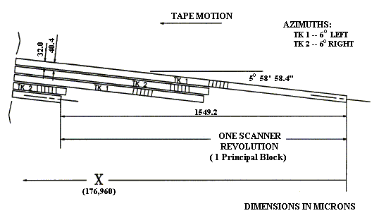 6.16.2.2 E Format. These formats originate from helical scanner implementations using two helical heads with wider track widths at 180° separation on the scanner. The heads are both read and write functionally. One set of read/write or write only electronics is required. Helical track dimensions are given in figure 6-11.  6.16.3 Data Storage. Data are recorded onto 12.65 mm (1/2 in.) wide magnetic tape using both rotating and fixed heads (see figure 6-12). The rotating heads record data in adjacent track patterns at an inclined angle to the normal tape motion. The fixed heads record data on tracks parallel to the tape motion. The fixed head tracks are used for control and servo purposes and do not directly record user data. 6.16.4 Physical Relationships. Maintaining high accuracy of the ratio between scanner rotational speed and tape speed (1.5492 mm (0.0610 in.) of tape motion per scanner rotation) is critical to maintaining the format geometry. Head and tape speed will vary accordingly with changes in the other two speed parameters. The three speed parameters vary linearly with desired user data rates. Parameters used with a user data rate of 32 Mbps (B) or 16 Mbps (E) are as follows:
6.16.5 Helical Track Organization. Each group of four helical tracks resulting from one complete revolution of the scanner (two helical tracks for the E formats) is termed a principal block on the tape. A principal block is the smallest increment of data that may be written to or read from the tape. Each principal block is assigned a unique number which is recorded as part of the helical track. Helical tracks containing user data begin with the number 1 and are sequentially incremented on the tape up to the capacity of the cartridge. Whenever new data are appended on a previously recorded cartridge, the new data are precisely located to begin with the next helical track location after the previous end of data point with no interruption or discontinuity in track spacing. 6.16.6 Recorded Information. The following subparagraphs contain additional information. 6.16.6.1 Add overhead bytes generated by error correction encoding algorithms. 6.16.6.2 Provide preamble and postamble patterns for isolation of the information at the beginning and ends of the helical tracks. 6.16.6.3 Provide clock synchronization patterns to facilitate clock recovery at the beginning of each helical track. 6.16.6.4 Add patterns throughout the helical track to maintain synchronization and counteract bit slips during data extraction. 6.16.6.5 Provide redundantly recorded principal block numbers for organizing data on the cartridge. 6.16.6.6 Include a user specifiable volume label for identifying the entire cartridge. 6.16.6.7 Add miscellaneous data used to convey information about the organization of data on the cartridge and within the helical tracks. 6.16.7 Recording Geometry and Physical Dimensions . Included in the following subparagraph are the recording geometry and the physical dimensions. 6.16.7.1 Tape Reference Edge. The tape reference edge for dimensions specified in this section shall be the lower edge as shown in figure 6-12. The magnetic coating, with the direction of tape travel as shown in figure 6-10, shall be the side facing the observer. 6.16.7.2 Helical Tracks. Contained in the succeeding subparagraphs are the helical tracks attributes. 6.16.7.2.1 Track Widths. The width of a written track shall be 0.032 mm ± 0.002 (0.0013 in. ± 0.000079) for the B formats and 0.058 mm ± 0.002 (0.0023 in. ± 0.000079) for the E formats. 6.16.7.2.2 Track Pitch. The distance between the center lines of any two adjacent tracks, measured perpendicular to the track length, shall be 0.0404 mm (0.0016 in.) for the B formats and 0.0808 mm (0.0032 in.) for the E formats. 6.16.7.2.3 Track Straightness. Either edge of the recorded track shall be contained within two parallel straight lines 0.005 mm (0.0002 in.) apart. The center lines of any four consecutive tracks shall be contained within the pattern of four tolerance zones. Each tolerance zone is defined by two parallel lines which are inclined at an angle of 5° 58' 58.4" basic with respect to the tape edge. The center lines of the tolerance zones shall be spaced 0.0404 mm (0.0016 in.) apart for the B format and 0.0808 mm (0.0032) apart for the E format. The width of the first tolerance zone shall be 0.007 mm (0.00028 in.). The width of tolerance zones two, three, and four shall be 0.011 mm (0.0004 in.). These tolerance zones are established to contain track angle, straightness, and pitch errors. 6.16.7.2.4 Gap Azimuths. The azimuth of the head gaps used for the helical track recording shall be inclined at angles of ± 6° ± 15' to the perpendicular to the helical track record (see figures 6-10 and 6-11). For the E formats and for the first and third tracks of every principal block of the B formats, the recorded azimuth is oriented in the clockwise direction with respect to the line perpendicular to the track direction when viewed from the magnetic coating side of the tape. For the B formats, the second and fourth tracks of each principal block are oriented in the counterclockwise direction. 6.16.7.2.5 Track Guard Bands. The nominal unrecorded guard band between any two adjacent helical tracks shall be 0.008368 mm (0.0003 in.) for the B formats and 0.022737 mm (0.0009 in.) for the E formats. 6.16.7.2.6 Track Angle. The track angle shall be 5° 58' 58.4". 6.16.7.2.7 Track Length. The track length shall be 96.619 mm (3.80 in.). 6.16.7.2.8 Physical Recording Density. The maximum physical density of the recording shall be 1930 or 3776 flux transistors per millimeter (ftpmm) respectively for the 32 and 64 Mbps systems. 6.16.7.3 Longitudinal Tracks. The characteristics of the longitudinal tracks are described in the subsequent subparagraphs. 6.16.7.3.1 Servo Track. The servo track is located along the reference edge of the tape as shown in figure 6-12. The azimuth angle of the servo track head gap shall be perpendicular to the recorded track. The recording of the servo track is composed of a recorded pulse (nominally 0.0185 mm (0.0007 in.)) for each principal block on the tape. The recording shall achieve full magnetic saturation for at least half the pulse. The time duration of the pulse is determined by the tape speed to yield this physical dimension. During the interval between pulses, no magnetic recording occurs on the track. The pulse is timed to begin coincident with the midpoint of the principal block (the data channel switches from first to second head). The physical offset from the longitudinal head to the helical heads is shown in figures 6-10, 6-11, and 6-12 as dimension “X.” 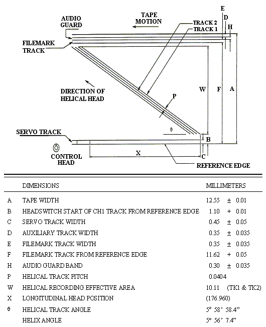 6.16.7.3.2 Filemark Track. The filemark track is located near the top of the tape as shown in figure 6-12. The azimuth angle of the filemark track head gap shall be perpendicular to the recorded track. The recording of the filemark track is composed of a series of pulses located in conjunction with the principal block to be marked. Each filemark is composed of three redundant pulses (nominal 0.005 mm (0.0002 in.)). The three pulses are typically spaced 0.029 mm (0.0011 in.) apart with a maximum span of 0.09 mm (0.0035 in.) from the beginning of the first to the beginning of the third. This triplet of pulses is for redundancy against tape flaws and on detection are treated as one filemark regardless of whether 1, 2, or 3 pulses are detected. The filemark pulses are associated with a specific principal block by initiating the first pulse between 4 to 5.5 msec after the midpoint of the principal block. (Data channel switches from first to second head.) 6.16.8 Tape Cartridge Format. The physical format of the recording along the length of the tape is shown in figure 6-13. Immediately following the physical beginning of tape (PBOT) is an unused portion of tape, followed by the cassette format zone which precedes the logical beginning of tape (LBOT). Principal blocks of user data shall be recorded between LBOT and the logical end of tape (LEOT), which precedes the physical end of tape (PEOT). 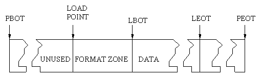 6.16.8.1 Load Point. The load point is defined as the first point after PBOT accessible by the recording system with the tape fully engaged to the scanner. 6.16.8.2 Format Zone. The format zone begins at the load point, precedes the LBOT, and consists of a minimum of 450 principal blocks recorded on the tape. It provides a run up area for the servo systems and principal block identification allowing precise location of the LBOT where user data begin. The zone must be prerecorded to prepare the cartridge to accept user data. This process involves locating at the load point and beginning recording as soon as tape speed servo lock is achieved. The principal blocks recorded are numbered beginning with a negative number and counting up until principal block 0 is recorded. Principal block 0 shall be the last recorded block in the format zone. Principal blocks recorded in the format zone do not contain user data or error correction coding (ECC) overhead bytes, but do contain the remaining miscellaneous information described in paragraph 6.16.6 and in the helical track data format descriptions. The volume label for the cartridge is irreversibly determined at the time the format zone is recorded. 6.16.8.3 Logical Beginning of Tape. The logical beginning of tape denotes the end of the format zone and the point at which principal blocks containing reproducible data begin. The first principal block containing useful information shall be assigned the number one. 6.16.8.4 Data Zone. Beginning with principal block 1 at LBOT and continuing through to LEOT, the data zone shall be the principal blocks which record user data as well as the added miscellaneous information to allow full reproduction and management of the data on the tape cartridge. 6.16.8.5 Logical End of Tape. The logical end of tape is a physical principal block count. The principal block count for the standard ST-160 tape cartridge is 210 333. 6.16.9 Helical Track Format. The format for writing data into a single helical track is shown in figure 6-14. The term "bits" refers to actual on tape bit cells. Each helical track begins with a preamble area consisting of 6216 bits of an alternating pattern of three 0 bits and three 1 bits for the 32 Mbps system or 9240 bits for the 64 Mbps system. This 6-bit pattern is repeated 1036 or 1540 times. The preamble is followed by a track synchronization area. This area provides for obtaining registration to the track data patterns. It is composed of four zones of 732 bits each with an alternating 0 and 1-bit pattern that facilitates clock recovery. Each of these four zones is followed by a 36-bit sync pattern. These sync patterns are described more fully in subparagraph 6.16.9.1. The track synchronization area ends with 24 bits of an alternating pattern of three 0 bits and three 1 bits. The central area is where actual user data are recorded in 138 data blocks for the 32 Mbps system or 276 data blocks for the 64 Mbps system. Each data block contains 205 5/6 modulation code frames of interleave data for a total of 1230 bits. 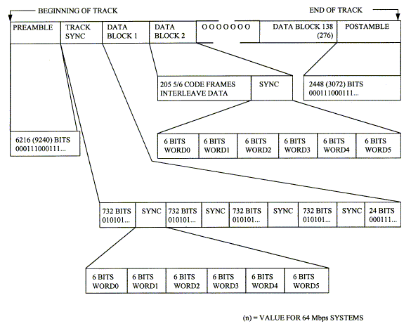 This data is followed by a 36-bit sync pattern. Sync patterns and interleave data are more fully described next. Each helical track ends with a postamble pattern of three 0 bits and three 1 bits. This is the same pattern as the preamble. Compiling all bits yields an overall track total of 186 468 tape bits for the 32 Mbps system and 364 824 tape bits for the 64 Mbps system. Since each contains 131 072 or 262 144 user bits, overheads are 29.7 and 28.1 percent. 6.16.9.1 Sync Patterns. Each helical track contains 142 or 280 sync patterns as shown in figure 6-14. Four of these are contained in the track sync area with the remaining 138 or 276 distributed at the end of each data block. These sync patterns provide registration to the bit sequence and allow management of bit slips. The track and data sync consists of 36 bits in the form of six 6-bit words. The first five words are the same for all sync words. They are
WORD5 defines which sync word is being issued in the following manner:
6.16.9.2 Data Blocks. Each helical track contains 138 or 276 data blocks which record the user data as well as miscellaneous information used in locating and managing data on the tape cartridge (see figure 6-14). The construction of these data blocks is performed by each channel’s data path electronics. Figure 6-15 illustrates a typical block diagram of a channel data path as described in the following subparagraphs. 6.16.9.2.1 Error Correction Encoding. An interleaved Reed-Solomon (RS) code is used for error detection and correction. An outer ECC is applied to written data first which is an RS (130, 128) for purposes of error detection only. An inner ECC is subsequently applied which is an RS (69, 65) for error detection and correction. The resulting encoded data is stored in a multiple page interleave buffer memory array containing 128 rows by (2x69) or (8x69) columns of encoded user data. For the outer ECC, incoming data is arranged in groups of 128 bytes each. The outer ECC encoder appends 2 check bytes to each 128 byte block. For the inner ECC, the 130 byte group resulting from the outer ECC is divided into two 65 byte blocks. The first 65 byte block (ECC codewords 1, 3, 5, ...) contains all user data while the second 65 byte block (ECC codewords 2, 4, 6, ...) contains 63 bytes of user data with the last 2 bytes being the check bytes generated by the outer ECC. The inner ECC encoder appends 4 check bytes to each 65 byte block. Operations in the RS encoder are performed using numbers in a finite field (also called a Galois field (GF)). The field used contains 256 8-bit elements and is denoted GF (256). The representation of GF (256) used is generated by the binary degree eight primitive polynomials. 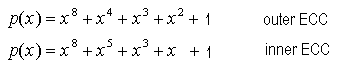 The ECC generator polynomials are 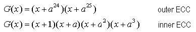 where "a" denotes the primitive element of the field. 6.16.9.2.2 Interleave Buffer. Encoding data from the two levels of ECC are stored in an interleave buffer memory. The architectures for this memory are shown in figure 6-16. This buffer allows interleaving of the encoder data. Interleaving spreads adjacent ECC code word bytes within a helical track for the 32 Mbps system to minimize the effect of burst error events. For the 64 Mbps system, interleaving spreads adjacent ECC codeword bytes within two helical tracks (two helical tracks per channel per principal block) to further minimize burst error effects. Data to and from the ECC are accessed along horizontal rows in the memory matrix. Data to and from tape are accessed along vertical columns in the memory. Each column in the matrix consists of 128 bytes which will constitute one block in the helical track format (see figure 6-14). 6.16.9.2.2.1 Exchange of Data with ECC. Addressing of the interleave buffer for exchange of data with the ECC for the 32 Mbps systems is
Addressing of the interleave buffer for exchange of data with the ECC for the 64 Mbps systems is
Each codeword is 69 bytes long. The address increments by hex 001 for each byte in a codeword. The first data byte sent to/from the ECC for each helical track is stored in location 000. 6.16.9.2.2.2 Exchange of Data To and From Tape . Addressing of the interleave buffer for exchange of data to and from tape for the 32 Mbps system is
Each data block is 128 bytes long. The address increments by hex 0100 for each byte in a data block. The first byte sent to/from tape for each channel 1 helical track is stored in location 0000. The first byte sent to/from tape for each channel 2 helical track is stored in location 0022. Addressing of the interleave buffer for exchange of data to/from the 64 Mbps system is
Each data block is 128 bytes long. The address increments by hex 0400 for each byte in a data block. The first byte sent to or from tape for both channels is stored in location 00000. The interleave buffer extends across both helical tracks in a principal block for each channel, thus the data block number “n” refers to the data block in the first helical track of the principal block and the data block number “n’ ” denotes the data block number in the second helical track of the principal block. 6.16.9.2.3 8 to 5 Conversion . Data being moved from the interleave buffer to tape is read from the memory in 8-bit bytes and is immediately converted to 5-bit groups in preparation for modulation coding. During reproduction this conversion occurs in reverse fashion. The algorithm for conversion is detailed in Metrum Document Number 16829019. 6.16.9.2.4 Miscellaneous Information Inclusion . Each data block in the helical track includes one additional bit added to the data set prior to modulation coding. Each data block removed from the interleaved buffer memory consists of 128 bytes of ECC encoded user data totaling 1024 bits. Conversion from 8-bit bytes to 5 bit groups results in 204 groups plus 4 bits. A miscellaneous information bit is added to each data block as the 1025th bit to complete 205 full 5-bit groups. Miscellaneous information is currently defined only in the first helical track of each principal block. The remaining three helical tracks (1 in the E format) contain no defined miscellaneous bits and are reserved for future expansion. Any reserved miscellaneous information bits shall be recorded as 0 bits. The defined purposes of miscellaneous information bits in the first helical track of each principal block are
6.16.9.2.5 Modulation Code. Data is encoded using a 5/6 modulation code that has a spectral null at dc. The coding algorithm employed has a code word digital sum (CWDS) maximum of + 2 with a maximum run length of 6 bits. The 205 5-bit groups resulting from the 8 to 5 conversion (including the inserted miscellaneous bit) undergo this coding to form the final 5/6 code frames that are physically recorded in the data blocks of the helical track format. The algorithm for coding is detailed in Metrum Document Number 16829019. |
|
Footnotes 3. Metrum Document Number 16829019, VLDS Magnetic Tape Recorder/Reproducer Tape Cartridge Format Specification. Available from Metrum, Inc., 4800 E. Dry Creek Road, Littleton, Colorado 80122. |