|
IRIG 106-99 CHAPTER 6 - MAGNETIC TAPE RECORDER AND REPRODUCER STANDARDS, Continued.... 6.1 Introduction 6.2 Definitions 6.3 General Consideration for Longitudinal Recording 6.4 Recorded Tape Format 6.5 Head and Head Segment Mechanical Parameters 6.6 Head Polarity 6.7 Magnetic Tape and Reel Characteristics 6.8 Direct Record and Reproduce Systems 6.9 Timing, Predetection, and Tape Signature Recording 6.10 FM Record Systems 6.11 PCM Recording 6.12 Preamble Recording for Automatic or Manual Recorder Alignment 6.13 19-mm Digital Cassette Helical Scan Recording Standards 6.14 Multiplex/Demultiplex (MUX/DEMUX) Standard for Multiple Data Channel Recording on 19-MM Digital Cassette Helical Scan Recorder/Reproducer Systems 6.15 Submultiplex/Demultiplex Standards for Multiple Data Channels on a Primary Digital Multiplex/Demultiplex Channel 6.16 1/2 Inch Digital Cassette (S-VHS) Helical Scan Recording Standards 6.17 Multiplex/Demultiplex (MUX/DEMUX) Standards for Multiple Data Channel Recording on ½ Inch Digital Cassette (S-VHS) Helical Scan Recorder/Reproducer Systems MAGNETIC TAPE RECORDER AND REPRODUCER STANDARDS Continued.... 6.10 FM Record Systems 6.10.1 Tape and Reel Characteristics 6.10.2 Tape Speeds and Corresponding FM Carrier Frequencies 6.10.3 FM Record/Reproduce Parameters 6.10.4 Speed Control and Compensation 6.10.5 FM Record Parameters 6.10.5.1 Deviation Direction 6.10.6 FM Reproduce Systems For these FM record systems, the input signal modulates a voltage- controlled oscillator, and the output is delivered to the recording head. High frequency bias may be used but is not required. These standards shall apply. 6.10.1 Tape and Reel Characteristics . Paragraph 7.1 and all related subparagraphs shall apply. 6.10.2 Tape Speeds and Corresponding FM Carrier Frequencies. See table 6-7. 6.10.3 FM Record/Reproduce Parameters. See table 6-7. Figure 6-7, ADARIO block format.
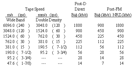
6.10.4 Speed Control and Compensation. Subparagraph 6.8.4 shall apply. Note that a separate track is always required for speed control and flutter compensation signals with a single-carrier FM system. 6.10.5 FM Record Parameters. For FM record systems, an input voltage of 1 to 10 V peak-to-peak shall be adjustable to produce full frequency deviation. 6.10.5.1 Deviation Direction. Increasing positive voltage gives increasing frequency. Predetection recorded tapes may be recorded with reverse deviation direction because of the frequency translation techniques employed. 6.10.6 FM Reproduce Systems. Output levels are for signals recorded at full deviation. In wide band and double density FM systems, the output is 2 V peak-to-peak minimum across a load impedance of 75 ohms ±10 percent. Increasing input frequency gives a positive going output voltage. 6.11 PCM Recording 6.11.1 Predetection PCM Recording 6.11.2 Post-Detection PCM Recording 6.11.3 Serial High-Density Digital Recording 6.11.4.1 PCM Codes 6.11.4.2 Bi 6.11.4.3 RNRZ-L Code 6.11.4.4 Record Parameters 6.11.4.5 Reproduce Parameters 6.11.4.5.1 PCM Signature 6.11.4.5.2 Phase Equalizer 6.11.4.6 Magnetic Tape 6.11.4.7 Tape Copying 6.11.4.8 PCM Bit Synchronizer The PCM signals may be successfully recorded using several different methods. Methods included in these standards are predetection recording, post-detection recording, and serial high-density digital recording (HDDR). Parallel HDDR methods are not included. 6.11.1 Predetection PCM Recording. This method employs direct recording of the signal obtained by heterodyning the receiver IF signal to one of the center frequencies listed in table 6-6 without demodulating the serial PCM signal (see figure 6-4). The maximum recommended bit rate for predetection recording of NRZ data is equal to the predetection carrier frequency, for example, 900 kb/s for a 900 kHz predetection carrier. The maximum recommended bit rate for predetection recording of bi-phase (Bi 6.11.2 Post-Detection PCM Recording. The serial PCM signal (plus noise) at the video output of the receiver demodulator is recorded by direct or wide band FM recording methods without first converting the PCM signal to bi-level form (see figure 6-4). Table 6-8 lists maximum bit rates versus tape speed for these recording methods. The minimum recommended reproduce bit rates are 10 kb/s for post-detection direct Bi
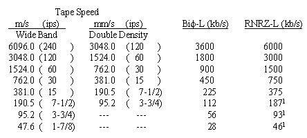
6.11.4 This paragraph deals with standards for direct recording of PCM telemetry data using a wide band analog instrumentation recorder or reproducer system. Direct recording is described in paragraph 6.8. The recommended PCM codes, maximum bit rates, record and reproduce parameters, and the magnetic tape requirements are also described. 6.11.4.1 PCM Codes. The recommended codes for serial high-density PCM recording are bi-phase level (Bi
6.11.4.3 RNRZ-L Code. The RNRZ-L code is recommended for direct recording under any of the following conditions: the bit rate of the data to be recorded exceeds the maximum recommended bit rates for Bi 6.11.4.3.1 To minimize baseline wander anomalies, RNRZ-L is NOT recommended if the reproduced bit rate is less than 200 kb/s. 6.11.4.3.2 The RNRZ-L shall be implemented using a 15-stage shift register and modulo-2 adders (see figure 6-5). The randomized bit stream to be recorded is generated by adding (modulo-2) the input bit stream to the modulo-2 sum of the outputs of the 14th and 15th stages of the shift register. In the decoder, the randomized bit stream is the input to the shift register (see figure 6-5). 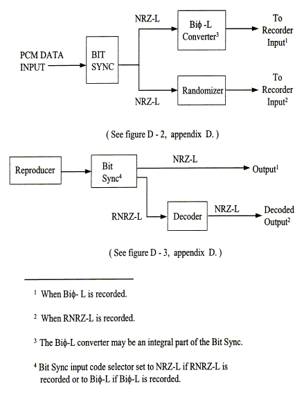 6.11.4.4 Record Parameters. The record parameters are explained in the following subparagraphs. 6.11.4.4.1 High-density PCM data shall be recorded in compliance with the direct record parameters detailed in subparagraph 6.8.1 including the use of an ac bias signal level which produces the required 2 dB over-bias condition. 6.11.4.4.2 The peak-to-peak level of the PCM input signal shall be equal to twice the rms value of the signal amplitude used to establish the standard record level with a tolerance of ±25 percent (see subparagraph 6.8.2). 6.11.4.4.3 The signal to be recorded must be bi-level. Bi-level signals are signals where only two levels are present. Therefore, signals containing noise must be converted to bi-level signals before they are recorded. 6.11.4.4.4 To minimize the effects of tape dropouts, serial high-density digital data should not be recorded on the edge tracks of the tape. 6.11.4.5 Reproduce Parameters. All reproduce parameters in subparagraph 6.8.3 shall apply. 6.11.4.5.1 PCM Signature. A PCM signature should be recorded before or after or both before and after the data to provide a method for adjusting the reproduce head azimuth and the reproducer equalizers. The data rate of the PCM signature should be the same as the rate of the data to be recorded (see paragraph 7.0, appendix D for tape signature recording). 6.11.4.5.2 Phase Equalizer. Correct phase equalization is very important to the reconstruction of the serial high-density digital data. Adjustable phase equalizers are desirable but not mandatory. 6.11.4.6 Magnetic Tape. High-density digital (HDD) magnetic tapes are recommended; however, wide band instrumentation tapes can be used on recorder and reproducer systems with 1.27 mm (0.050 in.) track widths (see chapter 7). 6.11.4.7 Tape Copying. The following practices are recommended when making copies of original data tapes. 6.11.4.7.1 Convert data reproduced from the original tape to a bi-level signal prior to recording a copy. 6.11.4.7.2 Align reproduce head azimuth to original tape. 6.11.4.7.3 Adjust reproducer equalizers correctly. 6.11.4.7.4 Prior to recording the copy, use the recorded PCM signature to optimize the quality of the reproduced data. 6.11.4.8 PCM Bit Synchronizer. The PCM bit synchronizer should contain circuitry to reestablish the baseline reference PCM signal (a dc restorer circuit). This circuit is essential when reproducing RNRZ-L at reproduced bit rates less than 1 Mb/s. The PCM bit synchronizer loop bandwidth should be selected for optimum performance between 0.1 and 3 percent of the bit rate.
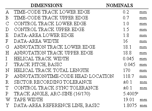
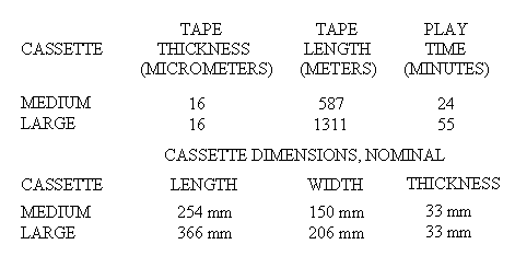
6.12 Preamble Recording for Automatic or Manual Recorder Alignment 6.12.1 Alignment, Direct Electronics 6.12.2 Alignment, FM Electronics A preamble (or postamble) may be recorded on the same tape as the data signal with known frequency and amplitude elements which will allow automatic or manual alignment of the signal electronics to optimize the performance of the playback system. Reproduce azimuth, equalization, and FM demodulator sensitivity may be adjusted at all available tape speeds. The preamble may be used for manual adjustment of any instrumentation magnetic tape recorder/reproducer (wide band and double density). Automatic adjustment requires a recorder/reproducer specifically designed with the capability to automatically adjust one or more of the following: reproduce-head azimuth, amplitude equalization, phase equalization, and FM demodulator sensitivity. The signal source may be internal to the recorder or may be externally generated. 6.12.1 Alignment, Direct Electronics. Direct electronics shall use a 1/11 band edge square wave for both manual and automatic alignment as given in appendix D. 6.12.2 Alignment, FM Electronics. The FM electronics shall use a 1/11 band edge square wave and ±1.414 Vdc or 0.05 Hz square wave for both manual and automatic alignment as given in appendix D. 6.13 19-mm Digital Cassette Helical Scan Recording Standards 6.13.1 Track Format 6.13.2 Tape and Cassettes 6.13.3 Recorder/Reproducer Input and Output These standards are for single-channel high-bit rate helical scan digital recorders using 19 mm tape cassettes. Bit rates of less than 10 megabits per second to 256 megabits per second or greater may be recorded and reproduced by equipment conforming to these standards. Interchange parties must, however, determine the availability at a particular site of the equipment required to meet particular data recording requirements. Compatibility between the recording device and the expected playback equipment must also be considered. 6.13.1 Track Format. The format recorded and reproduced by these systems shall be as specified in American National Standard For Information Systems 19-mm Type ID-1 Recorded Instrumentation Digital Tape Format, ANSI X3.175-19902 . Helical tracks employ azimuth recording wherein the head gap angle with respect to the recorded track center line is 90° + 15° for one scan and 90° - 15° for the adjacent scan. (See subparagraph 4.9.2 of standard X3.175-1990). Figure 6-6 and table 6-10 show details of the helical tracks and auxiliary longitudinal tracks for control, timing, and annotation in the ID-1 format. 6.13.2 Tape and Cassettes. Magnetic tape and 19-mm cassettes are specified in chapter 7. The magnetic tape shall meet the requirements for 850 oersted class (68,000 A/M). A tape base thickness of 16 um is normally employed. The recorder/reproducers shall be capable of using 19-mm cassettes that conform to the physical dimensions of medium and large cassettes as shown in table 6-11. Table 6-11 shows tape capacities and indicates the amount of time available for recording, assuming a data input rate of 240 megabits per second. 6.13.3 Recorder/Reproducer Input and Output. Data input and clock are required. The data input shall be in an 8-bit parallel, byte serial format, and the clock signal will be at the required byte rate. Data output will also be in 8-bit parallel format. 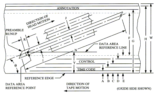
2. ANSI X3.175-1990. Available from American National Standards Institute, 1430 Broadway, New York, NY 10018. |
 If an appropriate PCM bit synchronizer is not available, the tape can be
copied directly; however, the SNR will be decreased.
